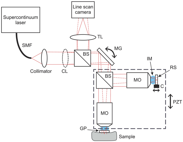
Fig. 1.
Schematic of the dual-mode LC-OCT system. SMF: single mode fiber; CL: cylindrical lens; BS: beamsplitter; MG: mirror galvanometer; MO: microscope objective; IM: immersion medium; RS: reference surface; C: piezoelectric chip; PZT: piezoelectric stage; GP: glass plate; TL: tube lens. The plain red lines represent the beam in the plane of the figure (the cylindrical lens has no effect in this plane). The dotted red lines represent the beam in the direction orthogonal to the plane of the figure. The dashed rectangle represents the part of the interferometer moved vertically under the action of PZT for B-scan imaging.

