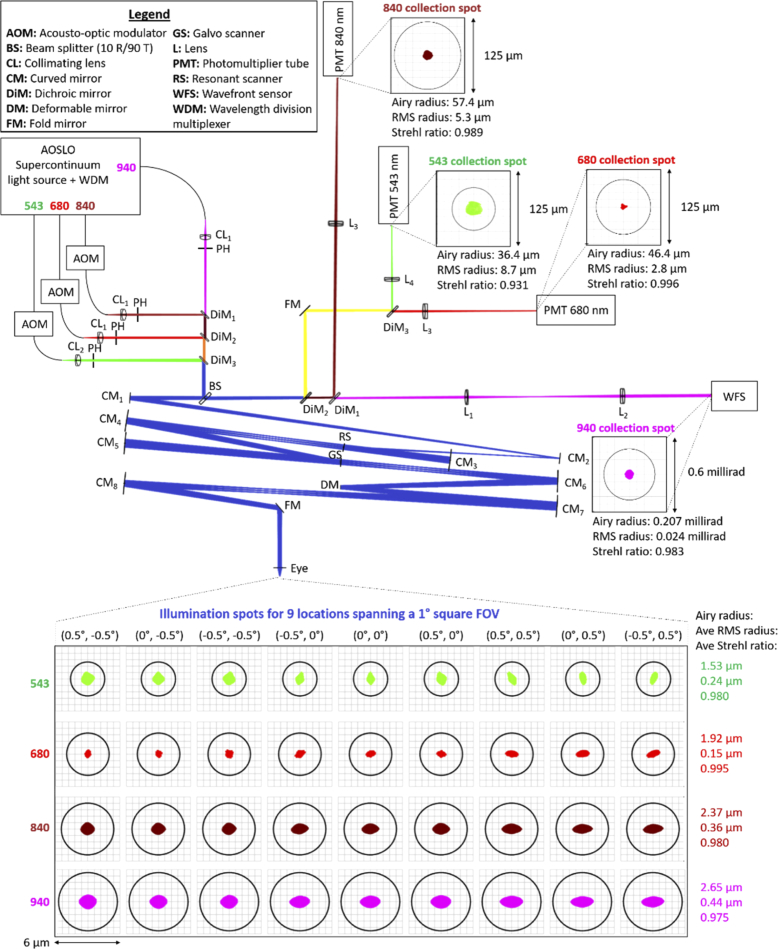
Fig. 1.
Multi-spectral AOSLO optical design and schematic. All optical components are labeled and described in the legend. Green, red, maroon, and magenta paths correspond to the optical paths of the 543 nm, 680 nm, 840 nm, and 940 nm channels, respectively. Paths with combined channels are blue (all wavelengths), orange (680nm + 840nm + 940 nm), brown (840nm + 940 nm), and yellow (543nm + 680 nm). Spot diagrams for all illumination spots spanning a 1° field of view (FOV) are shown below the schematic while those for specific collection channels are placed adjacent to the corresponding collection PMT or WFS as insets. Beneath each spot diagram are the Airy radius, root-mean-square (RMS) spot radius, and Strehl ratio. The model eye consists of a paraxial lens with a 16.7 mm focal length in air.

