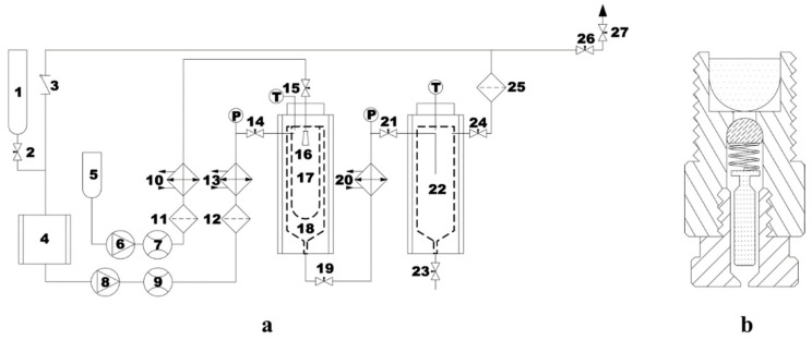
Figure 2.
Schematic diagram of the supercritical antisolvent (SAS) device (a) and the nozzle (b). (1) CO2 cylinder; (2, 14, 15, 19, 21, 23, 24, 26, and 27) valves; (3) check valve; (4) CO2 cooler; (5) liquid solution supply; (6) liquid pump; (8) CO2 pump; (7 and 9) flow meter; (10, 13 and 20) heat exchangers; (11, 12, and 25) filters; (16) nozzle; (17) stainless steel frit vessel of 200 nm; (18) precipitation chamber; (22) gas–liquid separation chamber.

