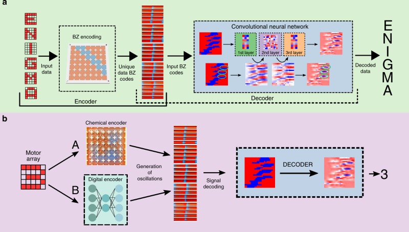
Fig. 4. Pattern classification and data encoding by BZ reaction and machine learning.
a Schematic showing the full working pipeline of our system. Initially the user selects an input pattern, and this pattern is binarized in a 5-by-5 matrix. This matrix is used as a source for the PWM generator, and this will eventually generate a global oscillation. These oscillations are then decoded when needed for pattern recognition. b Flow diagram of the pattern recognition process comparing the BZ oscillations produced by a digital encoder and by the BZ platform. The A path uses the BZ medium as described above. The B path uses a digital encoder that has been trained beforehand in order to digitally produce BZ oscillations from motor patterns. Once the oscillations are generated using the BZ platform or the digital encoder, they are correctly decoded using a decoder as shown in (a). Both in (a) and (b), a snapshot of an oscillation is shown. The vertical axis of this snapshot represents each of the 25 cells, while the horizontal axis represents time. This snapshot was made juxtaposing consecutive frames to better represent the temporal domain of the BZ oscillations.

