
Figure 1. Schematic diagram of the apparatus for continuous thermal lysis of bacterial cells and isolation of plasmid DNA.
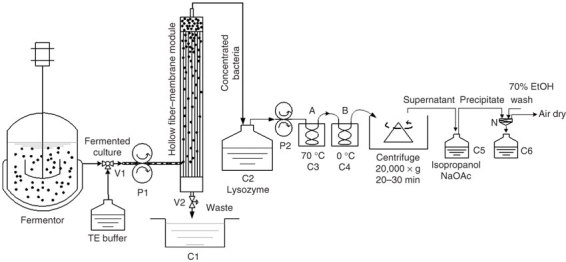
Cells are pumped from the fermentor into the hollow fiber-membrane module by peristaltic pump (P1) via a 3-way inlet valve (V1) and washed once with TE while inside the module. The waste liquid is discharged via an outlet valve (V2) into a waste container (C1). After closing the outlet valve V2, the concentrated cells are pumped from the top outlet of the module into a cell collection container (C2), where the cells are adjusted to the OD 600 nm of 100 by TE and treated with lysozyme before being pumped into the thermal exchange coils by a second peristaltic pump (P2); cells first pass through a thermal exchange coil (A) in a 70 °C water bath (C3) for continual thermal lysis, and are then immediately pumped through a second thermal exchange coil (B) in an ice bath (C4) and are collected in a container, which is also in the ice bath. After thermal treatment, lysed cells are centrifuged and the supernatant is mixed with 0.6 volume of isopropanol and 1/10 volume of NaOAc in container C5. Precipitated plasmid is collected on the 200 mesh nylon filter (N), whereas waste liquid is collected in container C6. Precipitates are washed with 50 ml of 70% EtOH and air-dried.