Figure 3.
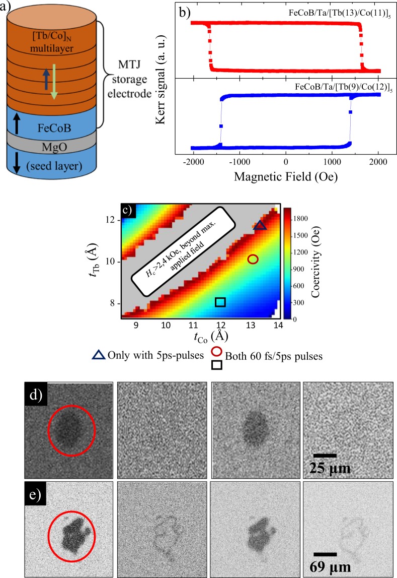
(a) Structure of half-MTJ stack used to optimize the magnetic coupling between the [Tb(10 Å)/Co(12 Å)]5 multilayer and the CoFeB electrode. (b) Hysteresis loop of the CoFeB/Ta/[Tb(tTb)/Co(tCo)]5 stack measured on opposite sides of the compensation region. (c) Coercivity map of the half-MTJ along the Tb and Co thickness wedges. The regions enclosed by the symbols indicate the three regions of the CoFeB/Ta/[Tb(tTb)/Co(tCo)]5 structure in which all-optical switching was achieved using different pulse durations: ▵: [Tb(11 Å)/Co(13 Å)]5, ○: [Tb(10 Å)/Co(13 Å)]5 and □: [Tb(8 Å)/Co(12 Å)]5 as indicated. (d–e) Background-corrected magneto-optical images demonstrating successful single-shot all-optical switching of magnetization in the CoFeB/Ta/[Tb(10 Å)/Co(13 Å)]5 stack using (d) ps- and e) fs-long laser pulses in with an incident fluence of 4.7 mJ/cm2 and 3.5 mJ/cm2 respectively.

