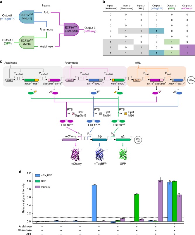
Fig. 5. Integrated intein-based logic circuit for selective detection of multi-input combinations.
a–c The schematic (a), truth table (b), and genetic design architecture (c) of the three-input three-output integrated logic circuit. Each input induces the expression of non-complementary split ECF-split intein N- and C-terminal chimeric protein proteins. An output is produced in the presence (+) of two inputs and in the absence (−) of the third input, via ECF trans-splicing and subsequent cognate promoter activation, but not when the system is exposed to only one input or in the absence of all inputs. The presence of the three inputs results in full activation of the system and the three outputs are expressed. d Relative fluorescence intensities of E. coli cells carrying the integrated logic circuit, measured 8 h after cultures exposed to the eight possible input combinations, normalized to maximum output signal of each reporter (see Supplementary Fig. 26). Bars represent the mean of three biological replicates (n = 3), error bars correspond to s.d. and the horizontal dotted line denotes 10% of the maximum signal output. Source data are provided as a Source Data file.

