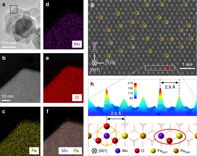
Fig. 1. EDX mapping and AC-STEM images of Mo1/Fe2O3.
a TEM image of Mo1/Fe2O3. b AC-STEM, and c–f EDX mapping images of the selected area (black dashed rectangle) in a. g AC-STEM image of Mo1/Fe2O3. h Intensity surface plot and the corresponding structural model of the selected area (white dashed rectangle) in g. The Mo loading is 1.3 wt% with respect to α-Fe2O3. The purple, red, yellow, and brown balls represent Mo atoms, O atoms, surface Fe atoms (Fesurf), and subsurface Fe atoms (Fesub), respectively. Selected single Mo atoms and dinuclear Mo1-Fe1 sites are marked by the yellow circles and the red ellipses, respectively.

