Fig. 1.

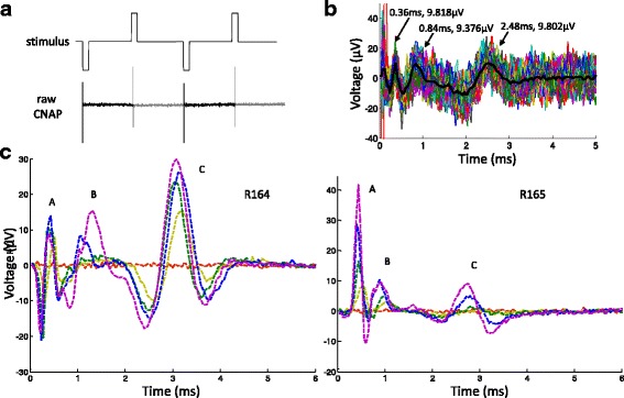
Vagal nerve response to stimulus. a Sample stimulus waveform (not to scale) and raw vagal recording. The darker segment of the recording represents the signal during the cathodic phase; the lighter segment represents the signal during the identical anodic phase half a period later. Two periods of alternating phases are shown. The spikes are due to stimulus artifacts, whose magnitudes were on the order of mV to V, depending on the stimulus intensity. b Sample processed CNAP. Summing the cathodic phase with the anodic eliminated the artifact. The summed segments (dotted traces) were then averaged to produce the estimated CNAP (thick, solid trace) for the trial. The three prominent peaks are labeled. c Sample CNAP series from the same stimulus waveform at different current amplitudes. As current increased, the peak heights (magnitude on the order of μV) increased as well. Peak designations are annotated. Data from two animals (R164 and R165) are presented to demonstrate variations in CNAP morphology
