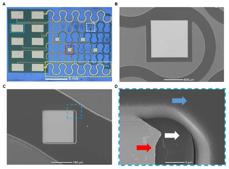
Figure 3. The electronic device.
A. Macro image of the complete fabricated device. A large drug release electrode is highlighted in red, a small recording electrode is highlighted in white, a large serpentine counter electrode is highlighted in yellow and a pad for external data acquisition and stimulation is highlighted in cyan. B. Scanning electron micrograph of the large electrode for drug release. C. Scanning electron micrograph of the small, recording electrode used for sensing cardiac cell extracellular signals. D. A Zoom-in image of the highlighted area in C, showing the bottom polyimide layer (white arrow), gold electrode pad (red arrow) and top polyimide layer (blue arrow).

