
Fig. 3. Nano-Auger–EBSD and TEM analysis of the CBE-processed steel.
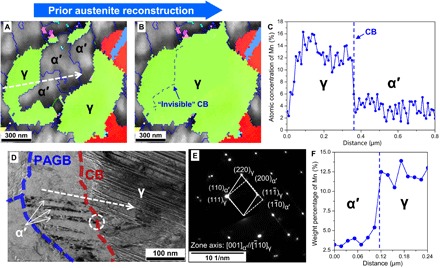
(A) Inverse pole figure map of austenite combined with image quality map of martensite. (B) Prior austenite reconstruction of (A) showing that the martensite blocks in the center share the same parent austenite orientation with the surrounding austenite. Blue and green lines in the EBSD maps correspond to high- and low-angle GBs, respectively (misorientation of ≥15° and between 5° and 15°, respectively). (C) Mn concentration profile obtained by nano-Auger line scan along the white line in (A), further confirming that the CB hinders martensitic transformation. (D) TEM bright field micrograph showing nanocrystalline martensitic laths stop at the CB. Prior austenite grain boundary (PAGB) represents prior austenite GB. (E) Corresponding selected area diffraction pattern in the marked area in (D) showing the near Nishiyama-Wassermann relationship between α′ and γ on both sides of the CBs due to having the same parent austenite. (F) Mn concentration profile obtained by TEM-EDS line scan along the white line in (D).