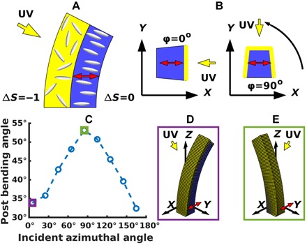
Fig. 3. Light-phobic bending for director in the plane of the substrate.

(A) Schematic of light-phobic bending. Disruption of the nematic state near the illuminated face will cause that region to expand vertically when the director is in the plane of the substrate. This will, in turn, cause the post to bend backward, away from the light. (B) Rotational variation of response. An overhead view of the post shows that we now have an additional degree of freedom as the light source is rotated relative to the director. To test the dependence on this coordinate, we simulate multiple configurations where the nematic director (red arrows) is oriented along the x axis and the light source (yellow arrows) is rotated around it. (C) Dependence of bending on incident azimuthal angle. Simulations represent posts of height 150 μm and width 25 μm, responding to a light source 30° from vertical. The light-averse response is strongest when the light is orthogonal to the programmed nematic director. (D) Post at incident azimuthal angle of 5°. Here, the light is incident at an oblique angle to the nematic director and induces a small backward bending. (E) Post at incident azimuthal angle of 85°. Here, the light is nearly orthogonal to the nematic director and induces a larger degree of backward bending than for an azimuthal angle of 5°.
