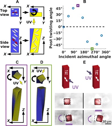
Fig. 4. Twisting behavior for director at 45° from the substrate.

(A) Schematic of illuminated post. When the illuminated region transitions from a nematic to an isotropic state, the angled orientation of the director will cause it to deform into a parallelogram. This will produce a shearing at the top of the post, causing it to twist. For this particular angle of the incident light, the induced twist is right-handed, as indicated by the curved arrow in the top view. (B) Micropost twist angle versus azimuthal angle of incident light. As the light source is moved counterclockwise around the post, it first produces right-handed (positive) twisting and then left-handed (negative) twisting, with no twisting at 0° or 180° from the x axis. (C) Overhead and side view of the micropost for an incident azimuthal angle of 125°. Here, light incident on the +y face produces right-handed twisting. This corresponds to the data point outlined in purple in (B). (D) Overhead and side view of micropost for an incident azimuthal angle of 245°. Here, light incident on the −y face produces left-handed twisting. This corresponds to the data point outlined in green in (B). (E) Experimental observations of twisting of surface-anchored LCE microposts. For the director orientation of 45° from the vertical, the LCE microposts reversibly twist clockwise and counterclockwise, with handedness controlled by the direction of incident light, as predicted by the simulations.
