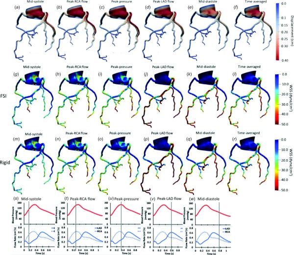
Fig. 2.

Displacement ((a)–(f)), wall shear stress contours in the FSI model ((g)–(l)), and rigid model ((m)–(r)) in 3D for a representative case. The contours are shown for participant 1 at midsystole (s), peak RCA flow (t), peak aortic pressure (u), peak LAD flow (v), and mid-diastole (w) in the cardiac cycle and time averaged through one cardiac cycle. Displacement of each coronary network is shown with respect to the original form (shown in gray). LAD: left anterior descending, RCA: right coronary artery.
