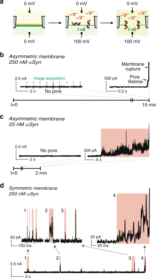
Fig. 2. αSyn pore formation on asymmetric and symmetric membranes.

a Schematic illustration of αSyn pore formation and monitoring. After membrane formation, αSyn is injected into the cytosolic channel and 100 mV is applied from the cytosolic to the extracellular face of the membrane. Upon pore opening, a non-zero current is measured. b, c Pore opening and asymmetric membrane rupture with 250 nM (b) or 25 nM (c) αSyn. Initially, there is no current, confirming the membrane sealed the hole separating the channels. After a few minutes, an increase in current is observed, showing a pore has opened between the channels (highlighted in red). Then, the membrane is broken as attested by out-of-range current (>10 nA). The little glitches (green arrows) observed in the “no pore” section of the current trace correspond to the image acquisition by the camera. d Pore opening with symmetric membranes. Current traces show that transient pores open and reseal frequently until the membrane is broken. a–d The lipid compositions are the same as in Fig. 1.
