Fig. 5.
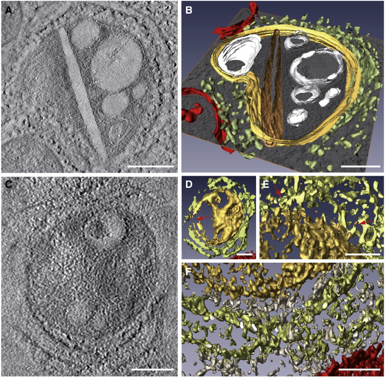
Analysis of ET volumes. Computational tomographic slices (A and C) and 3D models after segmentation and visualization with AMIRA (B and D to F). Color code is as follows: CPV, yellow; straight sheet, brown; RER, light green; mitochondria, red; vesicles and vacuoles, white; cytoplasm, grey. (A) A computational tomographic slice and the corresponding 3D model (B) of a CPV surrounded by the RER and containing a number of vacuoles, vesicles and a rigid straight sheet that is connected with the periphery of the CPV. The 3D model was built using a combination of masking, isosurface, and manual tracing using Amira segmentation tools. (C) A computational tomographic slice and two 3D models (D, E-F) of a CPV almost completely surrounded by the RER and filled with abundant material. The 3D model in (D) was built with a combination of masking and isosurface after strong filtering of the volume with nonlinear diffusion. The internal material of the CPV was solid rendered, keeping the vacuoles hollow, thus revealing the dense content of the vacuole at the top. This representation also shows that the CPV is opened to the cytosol (red arrow). The other 3D model in (E–F) shows contacts RER-CPV (red arrows in E, this area corresponds to the upper part of the model in (D)) and the “cytosolic macromolecules” (grey) filling the gap between the RER and the CPV (F, corresponding to the lower part of the model in (D)). This model was prepared as that in (D), but without nonlinear diffusion, to show the complex material surrounding the CPV. Bars, 200 nm in A–D; 100 nm in E and F.

