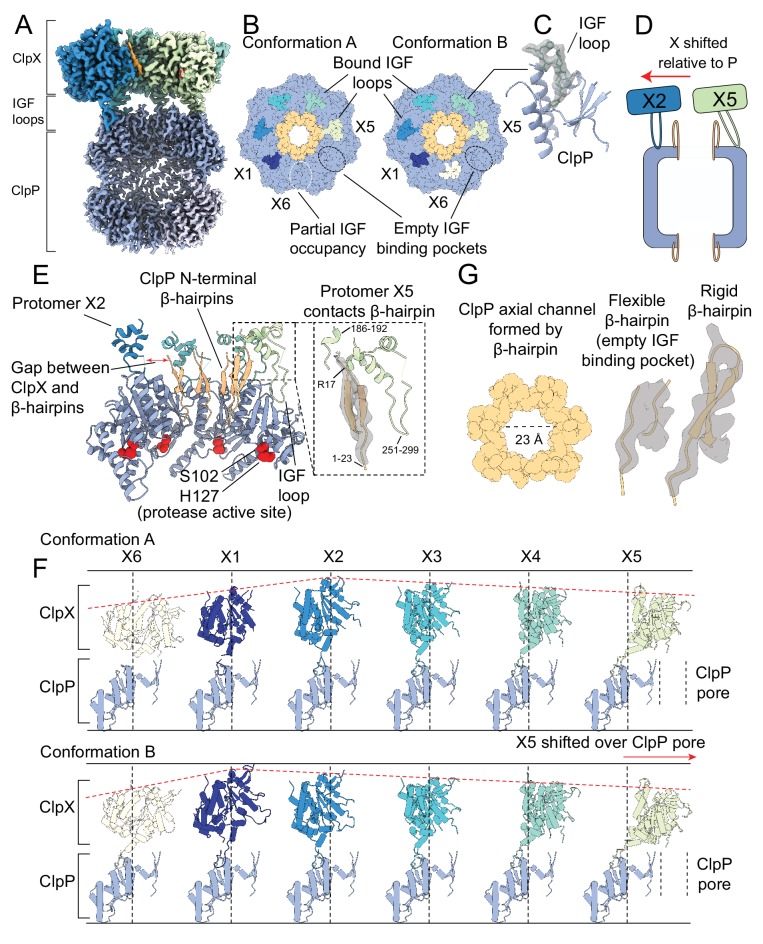
Figure 2. The interaction interface between ClpX and ClpP.
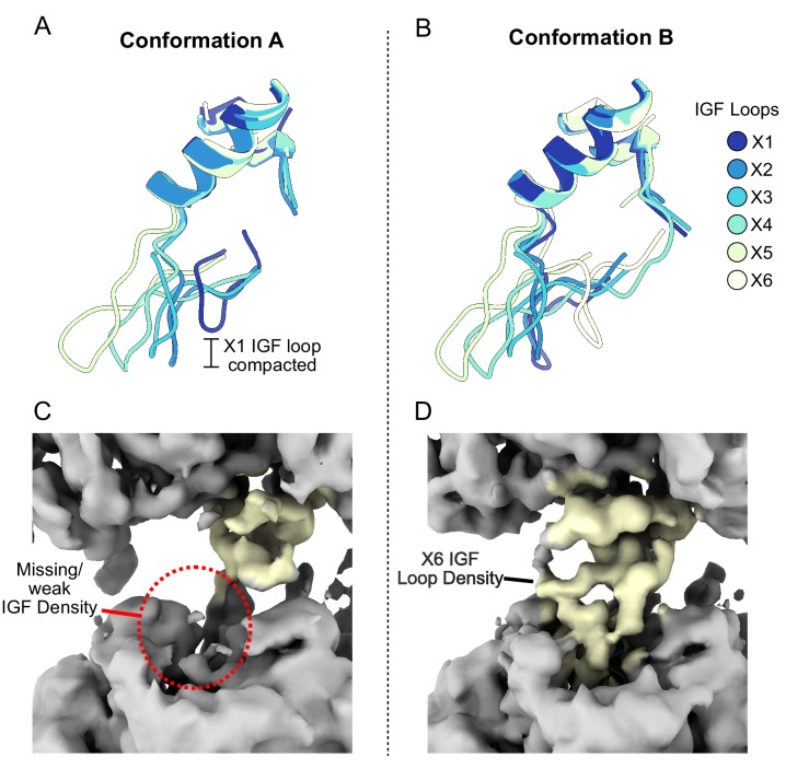
Protomer X1 occupies the US position in Conformation A and protomer X6 the LS position in Conformation B. (A) Cutaway density map of the overall architecture of the ClpXP interaction interface. (B) Models for the ClpP apical surface and the ClpX IGF loops (residues 265–275). The empty IGF-binding pocket (dotted oval) resides clockwise to the X5 protomer in both conformations. In Conformation A, an IGF loop was not built into the map for protomer X6 due to weak loop density (yellow dotted line). (C) Model in map fit for an IGF loop (grey), surrounded by regions of ClpP comprising the IGF binding site (blue). (D) Interaction of the ClpP N-terminal gates with ClpX. The X2 protomer moves away from the gates, while the X5 protomer directly contacts the gate of the ClpP protomer to which its IGF loop is bound, shown in (E). Inset shows the details of this interaction, with model in map fit for the ClpP β-hairpin. (F) Positions of ClpX protomers relative to ClpP. Images were generated by fitting all ClpP protomers to a common protomer and displaying the corresponding ClpX protomer. In both conformations, ClpX adopts a spiral arrangement relative to ClpP (dotted red line). In Conformation A, the X2 protomer is located at the top of the spiral, while in Conformation B the X1 protomer occupies the top position, ~7 Å higher than its position in Conformation A. The ClpX protomers rotate and translate relative to ClpP; protomers X2 and X3 sit nearly atop their ClpP protomers, while X4 and especially X5 show large deviations from this position (vertical lines), with X5 sitting overtop the ClpP axial pore. (G) View down the channel formed by the N-terminal ClpP β-hairpins (left); density and models for the most flexible and rigid β-hairpins (center and right, respectively).


