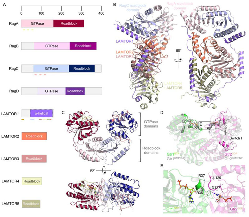
Figure 4. Structural biology of the small GTPases Rag and the Ragulator complex.
(A) Domain organization of the Rag GTPases and Ragulator complex components LAMTOR1-5. Pale green lines under RagA indicate, from N- to C terminus, the P-loop (residues 14-21), switch I (residues 39-45) and switch II (residues 60-67) regions. Pink lines under RagC similarly indicate the P-loop (residues 68-75), switch I (residues 91-99) and switch II (residues 114-122) regions. The brown bar at the LAMTOR1 N terminus indicates the palmitoylation and myristoylation motifs, while colored bars reflect the regions of interaction with other Ragulator-Rag components, colored according to the interacting proteins. (B) Crystal structure of Ragulator in complex with the Rag GTPase roadblock domain heterodimer (PDB ID: 6EHP). (C) Structure of the Rag GTPase heterodimer from the cryo-EM structure of the GATOR1-Rag GTPase complex (PDB ID: 6CES; EMDB: EMD-7464). RagA-bound GTP is shown as light green in stick representation. The P loop, switch I and II regions of RagA and RagC are colored as highlighted in A. (D) Comparison of the crystal structures of Gtr1GMPPNP-Gtr2GMPPNP (PDB ID: 3R7W) and Gtr1GTP-Gtr2GDP (PDB ID: 4ARZ), highlighting the conformational change of the Gtr2 switch I region. E. Gtr1-Gtr2 GTPase domain interface, as inset in D. Gtr1 residues R36 and R37 make direct contacts with the neighboring Gtr2 nucleotide binding pocket and the bound GDP itself. Polar contacts are indicated by dark gray dashed lines.

