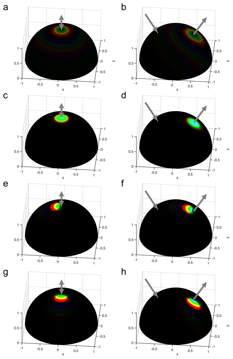
Figure 13.
Simulation of the angular optical response of the films obtained assuming = 0.1 and no anchoring at the interfaces with an incident light at (a,c,e,g) θ i = 0 and (b,d,f,h) θ i = 30°, and a magnetic alignment obtained for (a,b) γ = 0 (no H field), (c,d) γ = 10,βH = 0°,ψH = 0°, (e,f) γ = 10,βH = –30°, ψH = 0° and g-h) γ = 10,βH = –30°, ψH = –90°. The colored regions of the halfpheres visible at specific solid angles indicate the color observed in the direction pointing away from the half-sphere center. The incident and specularly reflected beam directions are represented with gray arrows.

