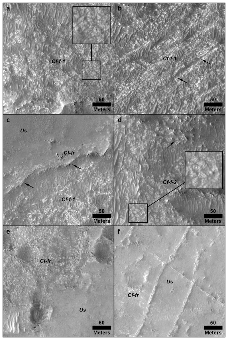
Fig. 9.
Examples of fractured and fractured rough units on the Jezero crater floor: (a) crater floor fractured 1 (Cf-f-1) with inset showing polygonal fractures, (b) crater floor fractured 1 (Cf-f-1) unit showing northeast-southwest trending furrows spaced ~ 50–75 m apart, (c) Topographic step (black arrows) that forms the contact between Cf-f-1 and adjacent crater floor fractured rough (Cf-fr) unit, (d) polygonal fractures (inset) and pock-marked texture (black arrows) of the crater floor fractured 2 (Cf-f-2) unit, (e) exposure of Cf-fr with little to no overlying undifferentiated smooth unit (Us) adjacent to area covered by Us, (f) Cf-fr displaying raised fractures and “moderate” coverage by Us

