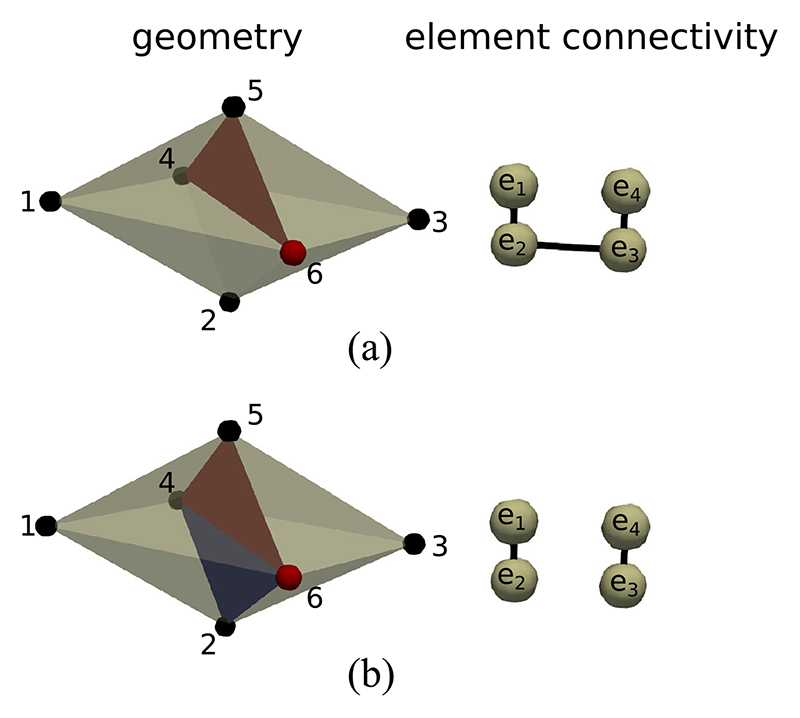
Fig. 3.
Example disconnection of a 3D connectivity graph in a tetrahedralized geometry. (a) The vertex 6 is visited by the algorithm. The split face (4, 5, 6) removes the link between e 1 and e 4. However, e 1 and e 4 are still connected via e 2 and e 3. (b) Face (2, 4, 6) is selected because the dot product of its normal with the normal of face (4,5,6) is minimal among all faces containing vertex 6. Elements e 1 and e 4 can now be isolated into two components e 1 – e 2 and e 3 – e 4. In general, several additional faces may be needed to split a 3D connectivity graph.

