
Fig. 3.
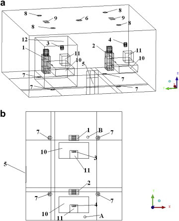
Configuration of the simulated office, a: three-dimensional view; b: top view (room width (X) 4.8 m, length (Y) 5.4 m, height (Z) 2.6 m; 1-the exposed person; 2-the polluting person; 3-RMP-E d = 190 mm; 4-RMP-P d = 190 mm; 5-DV inlet 500 × 1000 mm; 6-MV inlet d = 254 mm; 7-UFAD inlets d = 200 mm; 8-outlets d = 200 mm; 9-lamps; 10-tables; 11-monitors; 12-the exposed manikin’s occupied zone; A and B-measurement positions).