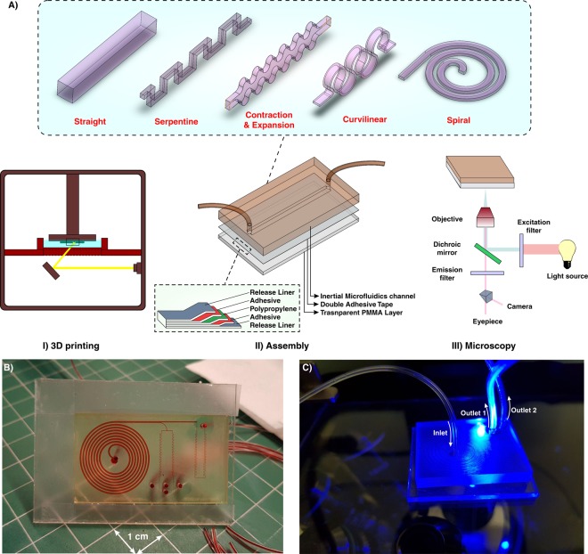
Figure 1.
(A) Schematic illustration of the proposed workflow for the fabrication of inertial microfluidic devices. I. The desired channel geometry was printed by a high-resolution SLA/DLP 3D printer II. After cleaning the part by isopropanol, it was bonded to a PMMA sheet by means of a double-coated pressure-sensitive adhesive tape. The entire process just takes less than two hours. III. Benefitting from the PMMA transparency, high-speed, fluorescent, bright field, or phase contrast microscopy can be performed from the bottom side of the channel (B) An actual complicated inertial microfluidic device containing a spiral and serpentine microchannel. (C) Fluorescent microscopy from the bottom side of the channel.

