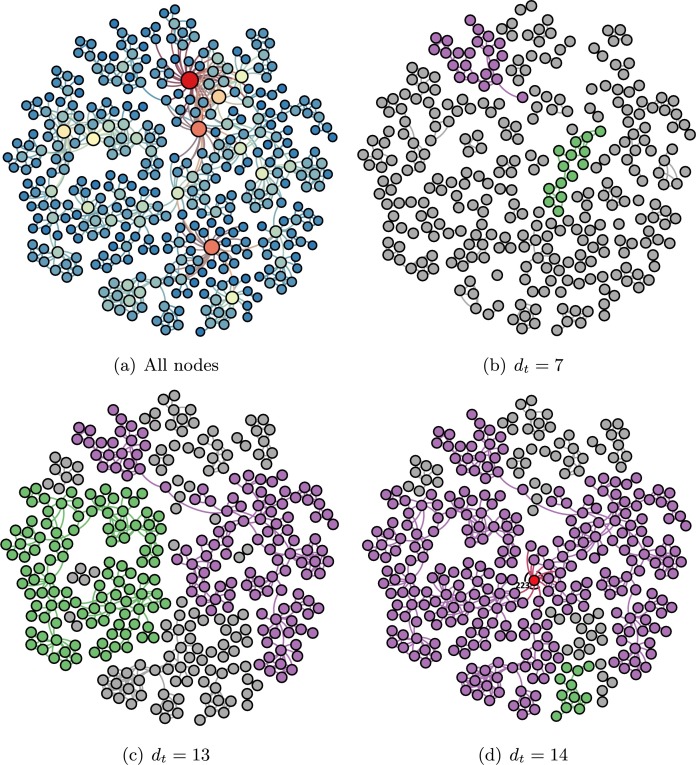
Fig. 1.
Critical node of the network. (a) A representation of all nodes. The size of a node is proportional to its degree: node 4 holds the largest degree. (b) A representation of subnetwork when . The largest and second-largest connected component are clarified by purple and green, respectively. And others with gray belong to the smaller connected component. (c) A representation of subnetwork when . (d) The critical node (red) is obtained when . (For interpretation of the references to color in this figure, the reader is referred to the web version of this article.)

