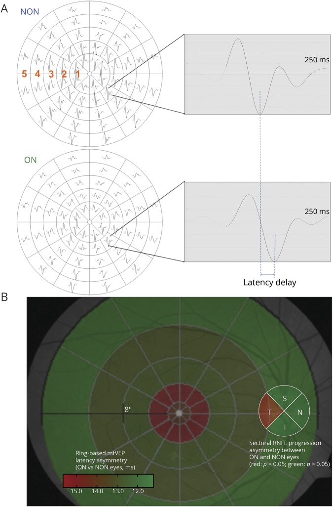
Figure 3. Accelerated tRNFL thinning reflects the topography of optic nerve demyelination in ON eyes.
(A) Representative mfVEP traces from a patient with MS with a history of unilateral ON. Significant latency delay is observed in the ON eye. Asymmetry of the latency of mfVEP was calculated for each of the 5 eccentricity rings to determine the pattern of optic nerve demyelination. (B) Optic nerve fibers projecting to rings 1–2 showed a significantly higher level of demyelination than those projecting to rings 3–5 (p = 0.0005, 2-way ANOVA). The central retinal area topographically corresponds to the RNFL in the temporal sector of the optic disc (shown in red). This result could explain the observation of accelerated tRNFL thinning in ON eyes compared with fellow NON eyes. Compared with traditional pVEP, mfVEP used in this study represents a superior technique. Because of opposite orientation of upper and lower calcarine cortices, the dipoles generating responses from stimulation of the upper and lower hemifields are opposite and, therefore, producing oppositely oriented waveforms, which results in a cancelation effect.40 Therefore, pVEP actually represents the difference between signals from upper and lower calcarine cortices. In addition, the majority of the pVEP power is generated by 3–5 central degrees of the visual field, practically ignoring the paracentral and midperipheral fields. ANOVA = analysis of variance; NON = non-ON; ON = optic neuritis; pVEP = pattern VEP; RNFL = retinal nerve fiber layer; tRNFL = temporal RNFL.

