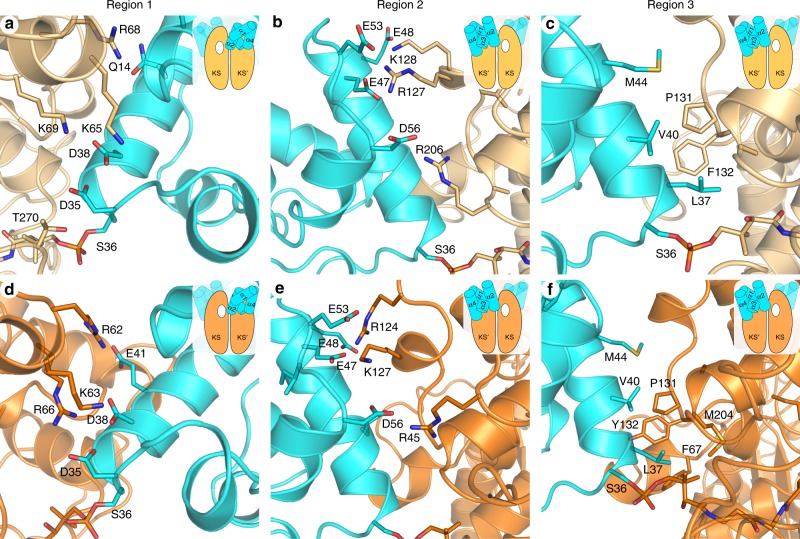
Fig. 3. AcpP–FabF and AcpP–FabB interface interactions.
The FabF (light orange) and FabB (bright orange) interfaces can be broken up into three regions, the first two are comprised of electrostatic interactions and the third is a hydrophobic patch. The above panels provide close-up views of these three regions and the cartoon inset provides context regarding the viewing angle and the positional relationship of AcpP (cyan) to the overall AcpP–KS complex. In addition, the white hole represents the active site to which the viewed AcpP is crosslinked as the majority of contacts are provided by the KS monomer not covalently crosslinked to AcpP. a A close-up view of the AcpP–FabF region 1 electrostatic interactions. b A close-up view of the AcpP–FabF region 2 electrostatic interactions. c A close-up view of the AcpP–FabF region 3 hydrophobic interactions. d A close-up view of the AcpP–FabB region 1 electrostatic interactions. e A close-up view of the AcpP–FabB region 2 electrostatic interactions. f A close-up view of the AcpP–FabB region 3 hydrophobic interactions.

