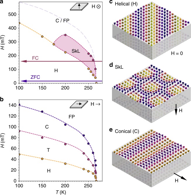
Fig. 2. Spin textures and magnetic phase diagrams of an FeGe lamella.
a, b Phase diagrams of the ~120 nm FeGe lamella for out-of-plane and in-plane applied magnetic field, respectively, as determined magnetic x-ray diffraction. Schematics of each field configuration are shown as insets. In a, boundaries between the helical (H) and skyrmion lattice (SkL) states are displayed by yellow and magenta dots. The expected boundary between the indistinguishable conical (C) and field polarised (FP) states is estimated by the purple dashed line. The zero-field cooling (ZFC) and field cooling (FC) procedures are indicated. In b, yellow, magenta and purple dots boundaries indicate the boundaries between the helical (H), helical rotation transition (T), conical (C) and field polarised (FP) states. c–e Schematic illustrations of the spin textures as they are expected to appear in a thin lamella.

