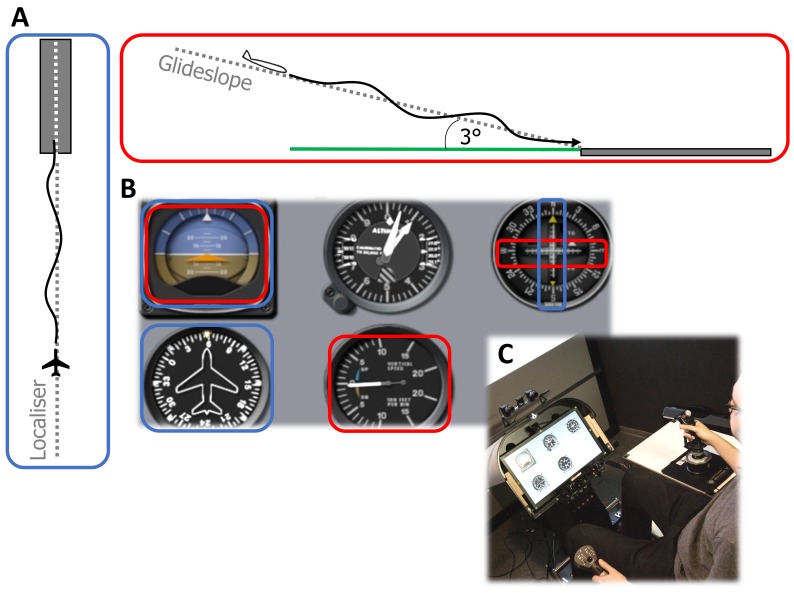
Figure 1.
A: Schematic representation of the instrument landing task from a side-on (red outline) and top-down (blue outline) view (not to scale). Participants attempt to follow the ideal vertical (glideslope) and lateral (localiser) paths using the cockpit instruments. B: Layout of the heads-down instrument panel showing, from top-left, in a clockwise direction: attitude direction indicator, altimeter, instrument landing course deviation indicator, vertical speed indicator, heading indicator. The instruments required to track the ideal: vertical path are outlined in red, and lateral path are outlined in blue. C: Photograph of the experimental setup showing the heads-down instrument panel, back-projection screen, control devices and eye-tracking cameras

