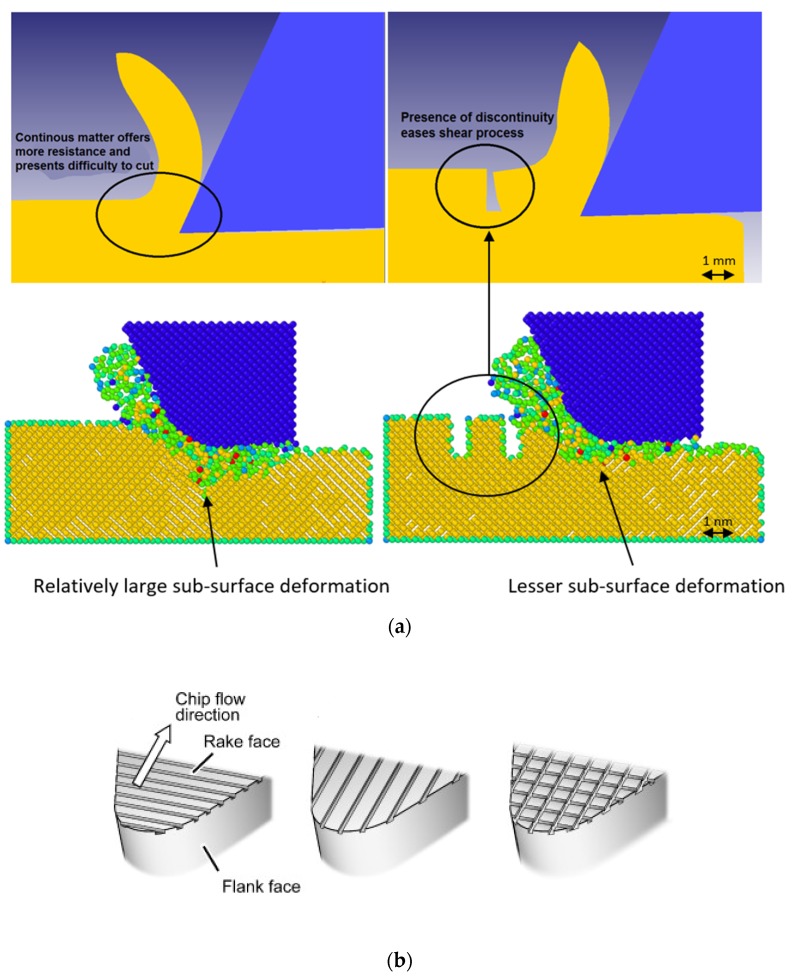
Figure 5.
(a): Schematic diagram indicating the differences between the mode of deformation during conventional machining and surface defect machining (SDM) observed through an FEA (Finite Element Analysis) simulation of hard steel and MD (Molecular Dinamics) simulation of silicon carbide, respectively; (b) effect of providing nanogrooves on the tool [78]. (a) Surface defect machining. (b) Providing nanogrooves on the tool.

