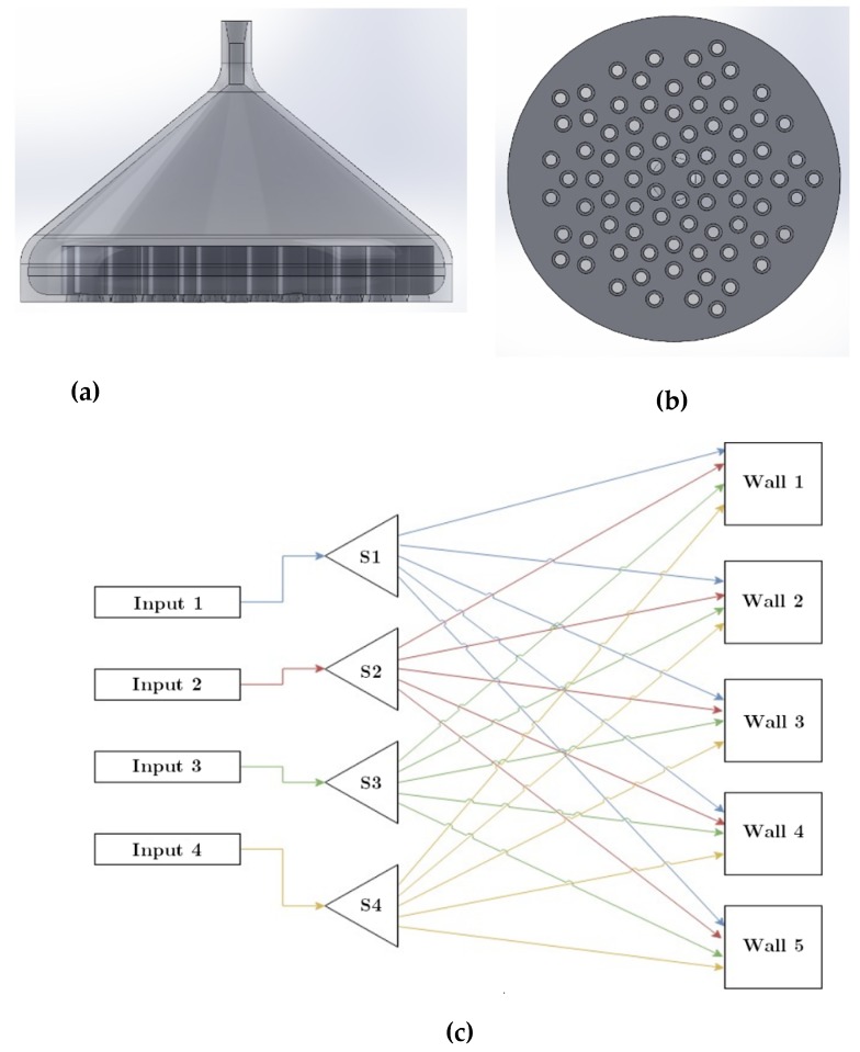
Figure 5.
(a) Side and (b) bottom views of the splitter. (c) Drawing of the connection from the pressure outlet of the pneumatic system to the splitters (S1, S2, S3, and S4) and then distributed to the unit cells of the metamaterial slabs (walls) in a closed-space system. Each line color represents the connection of each splitter to different cells of metamaterial slabs.

