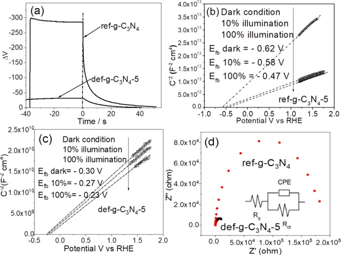
Figure 3.

(a) Open circuit photovoltage decay (OCVD) of ref-g-C3N4 and def-g-C3N4-5 electrodes. (b) Mott–Schottky plots of ref-g-C3N4 electrode at 1 kHz with 0–100% illumination. (c) Mott–Schottky plots of def-g-C3N4-5 electrode at 1 kHz with 0–100% illumination (MS plots at different frequencies are shown in Figure S9). (d) Impedance plots of ref-g-C3N4 and def-g-C3N4-5 electrodes at 0.2 V vs RHE in dark condition; the inset is the equivalent circuit of g-C3N4 electrode, where Rs is the system resistance, Rct is the charge-transfer resistance, and CPE is the constant phase element representing the double layer capacitor.
