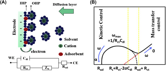
Figure 1.4.2.

(A) Schematic of a negatively charged electrified electrode wherein the cations are aligned on the interface (top). Electrical circuit elements correspond to each interface component (bottom), where Cdl is the double-layer capacitor, IHP is the inner Helmholtz plane, OHP is the outer Helmholtz plane, Rct is the polarization resistance, Rs is the solution resistance, and ZW is Warburg impedance. (B) A Nyquist plot of electrochemical impedance spectroscopy (EIS) measurement showing the semicircle and straight regions indicating kinetic and mass transfer control.
