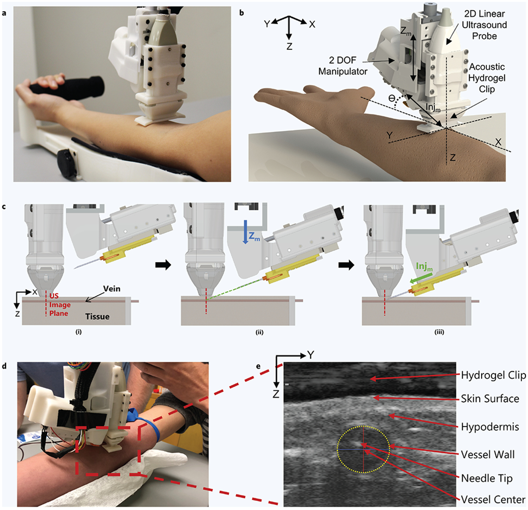
Figure 1. Robotic device set-up and operation.

(a) Hand-held venipuncture device. (b) Computer-aided design (CAD) displaying key components of the 2-degree-of-freedom (DOF) device. Angle of insertion (θ) is fixed at 25°. (c) Device operation. (i) Ultrasound (US) imaging plane provides a cross-sectional view of target vessel. (ii) Once a vessel is located by the device, the needle is aligned via the Zm – DOF motor (Zm = Z-axis motion). The Zm motor (blue arrow) is responsible for aligning the needle trajectory with the vessel depth (Z-axis) to ensure the needle tip reaches the vessel center exactly at the ultrasound imaging plane. (iii) Once trajectory is aligned, the needle is inserted via the Injm – DOF (Injm = Injection motion) motor (green arrow) and automatically halted once the tip has reached the vessel center. (d) Device positioned over the upper forearm during the study. (e) Ultrasound image depicting the needle tip present in the target vessel after a successful venipuncture. Vessel wall is identified by a yellow dashed ellipse. The Z-axis in the image indicates the vessel depth and the Y-axis indicates the sagittal position of the vessel. Positions of the vessel and needle tip are recorded with respect to the ultrasound transducer head (top of image).
