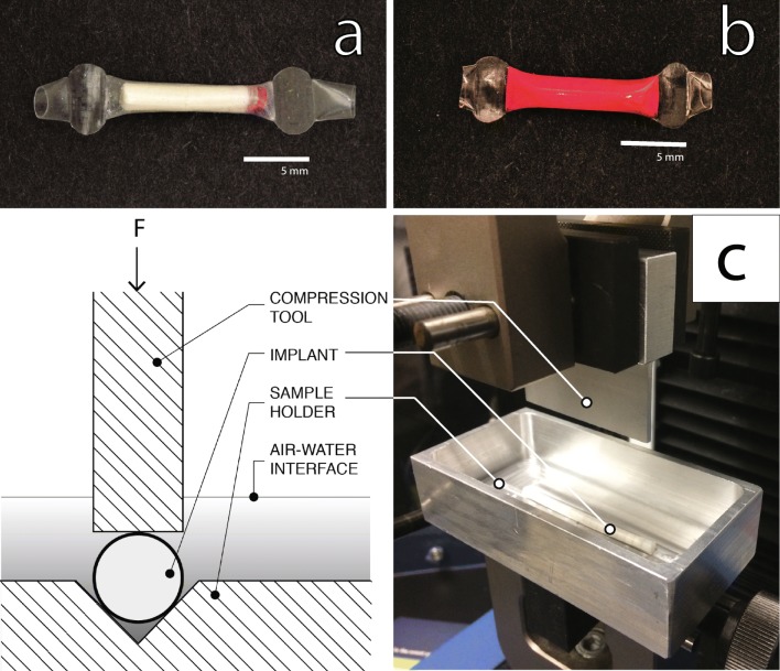
Fig. 2.
Implant and phase 2, compression testing. (a) A picture of a RITC-Dx - containing TAF implant before hydration. (b) A picture of RITC-Dx - containing TAF implant after hydration in PBS. (c) A cross-sectional view of phase 2 compression test tool and sample holder (left). Phase 2 implant mechanical testing apparatus with a compression tool and sample holder (right). The implant is placed in the V-shaped groove in the sample holder, and mechanical stress is applied by the compression tool.

