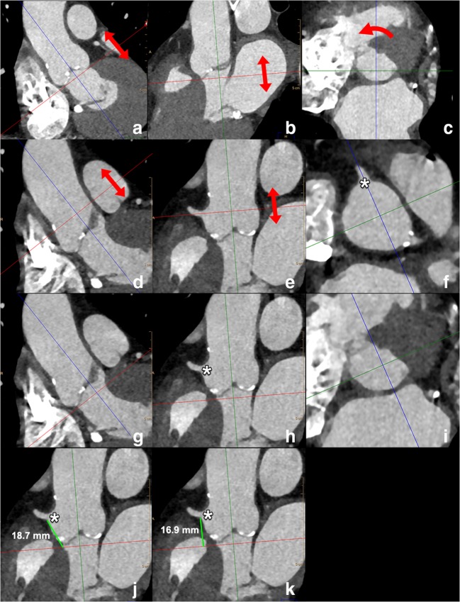
Fig. 14.
Standardised way to perform measurements of the distance of the annular plane to the ostium of the right coronary artery and left main. The starting points are the annular plane images (obtained through the steps outlined in Fig. 12) as displayed in a–c above. In this image stack, in plane with the annulus, the origin of the RCA is located by scrolling through the images in the direction of the aorta (arrows in a, b). Subsequently, the reference lines are rotated (curved arrow in c) in such a way that one of the reference lines passes through the RCA ostium (asterisk in f); then, by scrolling toward the LVOT (arrows in d, e), the annulus plane is again displayed (i) and in one of the two other panels (h), the origin of the RCA is visible (asterisk in h), as well as the reference line which corresponds to the annulus plane level (red line in h). The distance is measured as the distance of the lower border of the RCA ostium (asterisk in j, k) to the attachment of the coronary cusp (j) or perpendicular to the reference line of the annulus plane (k). For the distance of the annulus to the left main, the steps mentioned above are repeated

