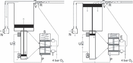
Figure 1.

Basic pneumatic principles of design (i). Left: the shuttle valve (S) is in the default position. The position of the small magnetised piston adjacent to the magnetic valve (A) has opened this valve causing the pressure in the line (P) to be vented to ambient. As no gas pressure is being applied to the base of the shuttle the spring has pushed the shuttle downwards. Oxygen enters via the inspiratory needle valve (I) and is directed to the base of the small piston, pushing it and the large piston to which it is attached upwards. This closes the unidirectional valve (V) causing oxygen enriched air to inflate the lungs via non‐return valve (N). Waste oxygen from the pneumatic mechanism is directed to the reservoir limb at (R). Right: valve (B) is permanently supplied with oxygen at 4 bar. At end‐inspiration the magnetic small piston triggers valve (B) which, via the unidirectional valve (U), pressurises the line (P) to 4 bar, causing the shuttle valve to change state. Oxygen at 4 bar now enters via the expiratory needle valve (E) pushing the small piston downwards, causing the large piston to draw oxygen enriched air from the reservoir limb (R) through valve (V). Meanwhile, the patient exhales by passive recoil of the lungs through the respiratory non‐return valve (N) to atmosphere. Waste oxygen from all parts of the mechanism is directed to the reservoir limb (R) to enrich the air within.
