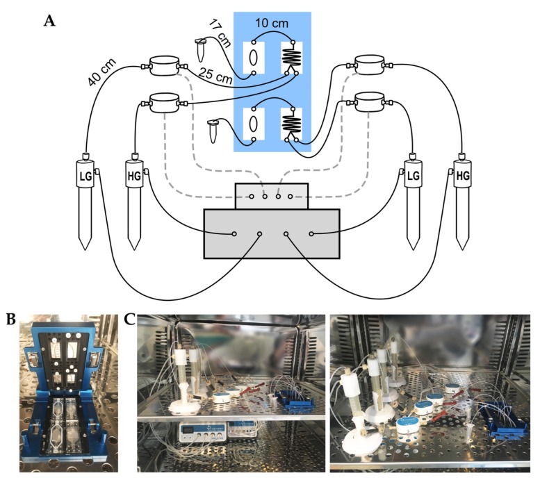
Figure 1.
Microfluidic perifusion system (MPS). (A) General scheme showing components assembly forming the MPS and the actual length of connection tubing: clamping system (blue box) containing two pairs of mixer and culture chips, flow Board (upper gray box), MFCS-EZ (lower gray box) and four flow rate units and reservoirs connected to mixer chips. (B) Picture of Micronit clamping system showing two mixer chips (right) and culture chips (left). (C) Picture of the MPS inside the incubator showing the entire system (left) and the reservoirs containing the perifusion solutions connected to the mixer and the culture chips (right).

