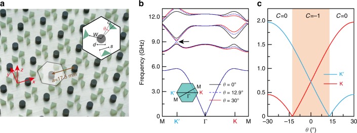
Fig. 1. Reconfigurable gyromagnetic photonic crystals (PhCs).
a Photograph of the PhC sample in a parallel-plate waveguide. The spacing between the upper and lower aluminum plates is 4 mm. Inset: schematic of a unit cell, which consists of a gyromagnetic cylinder (dark gray circle) and three dielectric right-triangular pillars (green triangles). The gyromagnetic cylinder has diameter d = 0.24a, and the right-triangular pillars have hypotenuse widths s = 0.28a. The distance between the unit cell center and nearest triangular vertices is w = 0.33a. The angle θ indicates the orientation of the triangular pillars within the unit cell, relative to the three primitive vectors of the hexagonal lattice. In the depicted configuration, θ = 12.9°. b PhC bandstructures under a 0.4 Tesla external magnetic field for θ = 0°, 12.9°, and 30°. For PhC at θ = 12.9°, an unpaired Dirac point appears at Κ′ (indicated by the black arrow). c Widths of the bandgap between the second and the third band at K and Κ′, as a function of θ. The bandgap at Κ′ (K) closes when θ = 12.9° (θ = −12.9°). For |θ|<12.9°, highlighted in light orange, the bandstructure has a topologically nontrivial bandgap, with the first band having a numerically calculated Chern number of C = −1 (Supplementary Fig. 3).

