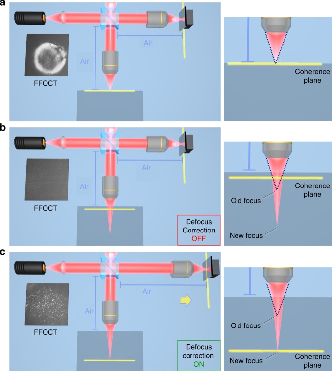
Fig. 3. Principle of defocus correction for matching the optical arms of FFOCT interferometer.
a The FFOCT interferometer is focused on the surface of the sample (blue square). The focus spot matches with the coherence plane. An FFOCT image from the surface is captured and defocus correction is not needed. b FFOCT interferometer is focused inside the sample. Due to Snell’s law the focus is extended. At the same time the coherence plane is shifted in the opposite direction due to the higher refractive index inside the sample than in the air. The focus spot and the coherence plane are mismatched and an FFOCT image cannot be captured without defocus correction. c The FFOCT interferometer is focused inside the sample and the focus is extended. The defocus correction procedure is performed: the reference arm is extended to put the coherence plane in the new location of the focus and the FFOCT image from inside of the sample is captured.

