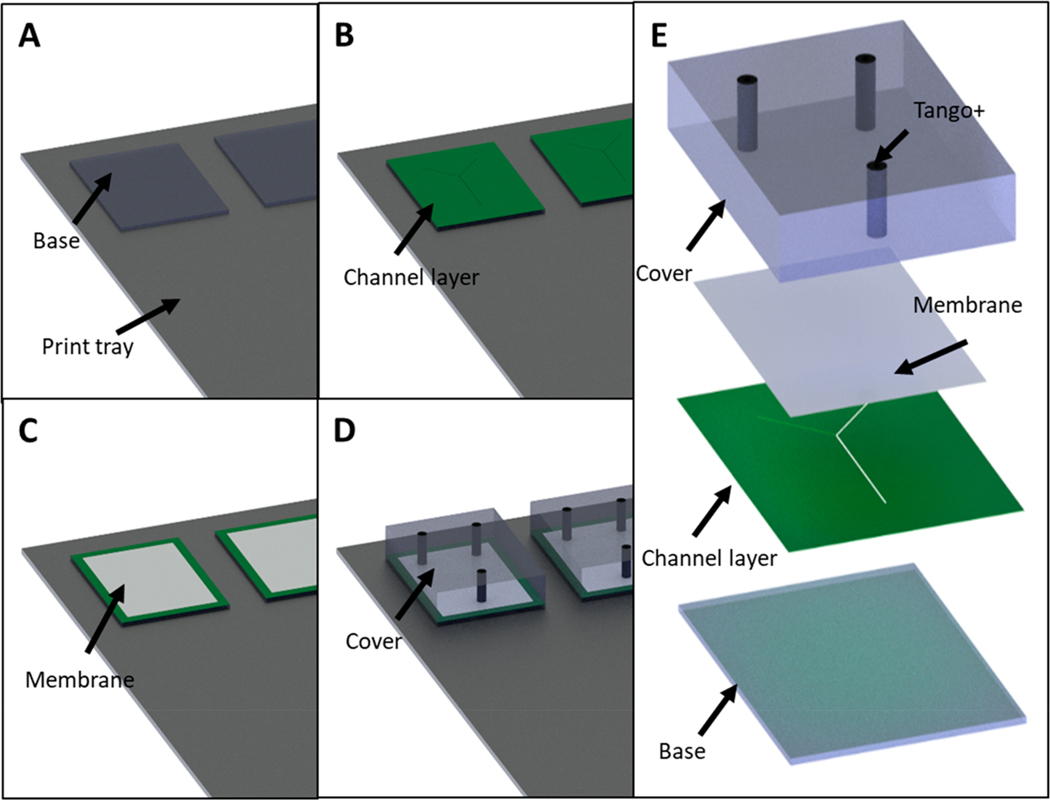
Figure 5.
CAD representation of the device fabrication using membrane support (A–E). In (A) the initial base model is printed directly onto the printer stage (i.e., no support material under the base). Next (B) the entire print stage is lowered by the height of the base model and a channel layer is printed. This is important to define the height of the channel as interpreted by the printer. In (C) the entire print stage is lowered again by the height of the channel layer and a polycarbonate membrane is laid such that it fully covers the channel area but not the entirety of the device. Finally (D), a new model (containing ports to access the channel) is printed directly on top of the base model, thereby enclosing the channel. (E) Exploded CAD view of the final Y shaped mixing chip.

