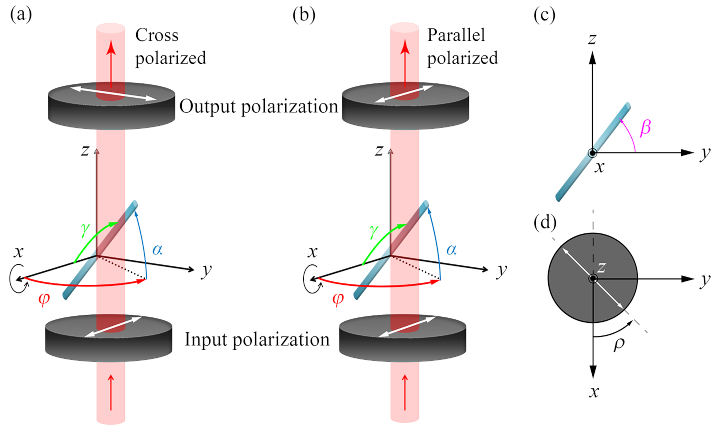
Fig. 1.
Schematic of the ODT sample arm geometry. (a) The orientation of the uniaxial sample is defined by the inclination angle and the direction angle . The sample is rotated around the -axis for tomographic measurement. The input polarization state is along the -axis, after which the parallel polarized -component (a) or the cross-polarized -component (b) of the complex wave is measured for each projection angle. The tomographic angle is defined with respect to the fiber orientation in the - plane. The angle of the polarizers is defined with respect to the axis.

