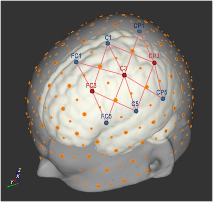
FIGURE 2.
Optode setup with three source and six detector optodes, placed on nine points according to the international 10-20 EEG system. Large orange dots represent reference points of the 10-20 system, whereas small orange dots represent reference points of the extended 10-10 EEG system (Oostenveld and Praamstra, 2001). The red lines represent 14 source-detector pairs (each forming an fNIRS channel). Image created using NIRSite (v.1) software (NIRx Medizintechnik GmbH, Berlin, Germany; RRID: SCR_002491).

