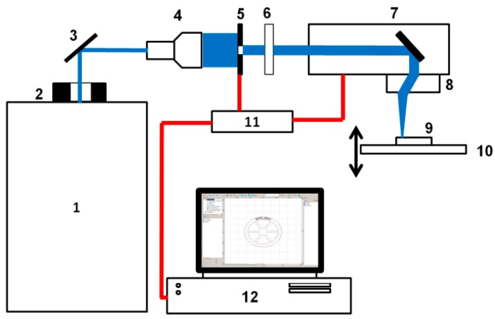
Figure 1.
Diagram of a laser system used, which was composed of 1—PL2210/SH/TH/FH picosecond laser (produced by EKSPLA); 2—Thorlabs shutter (Optical Beam Shutter SH05); 3—plane mirror; 4—laser beam polarizing damper; 5—Thorlabs BE05-355 optical beam expander with quintuple magnification; 6—iris diaphragm φ 5.8 mm; 7—SS-IIE10 355 nm galvanometric scanner produced by the company RAYLASE [7]; 8—S4LFT4010/126 SILL telecentric lens; 9—handle; 10—PT3/M Thorlabs sliding table XYZ; 11—RLC USB RAYLASE scanner driver; 12—computer with the weldMARK 3.0 software. The laser beam is marked in blue. Electric signal connections are marked in red.

