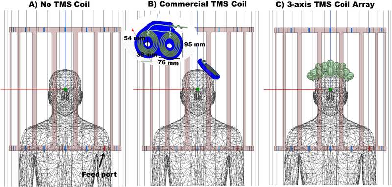
Figure 2.
Simulation set ups as seen in the simulation software HFSS. A) Reference model, with birdcage coil and the homogenous realistic human phantom. B) Setup showing the birdcage coil, the human phantom and the MR compatible commercial TMS coil, with bottom housing over the left hemisphere. C) Setup showing the birdcage coil, the human phantom and the sixteen 3-axis TMS coils over the phantom’s head distributed in a hexagonal pattern. No housing was drawn for this setup and therefore the elements are placed 5 mm above the scalp surface to account for the expected distance added by the chassis. For all three simulations, the feed ports are shown in red. One of the two ports is shown in the figure, the other is on the left side of the phantom and not visible.

