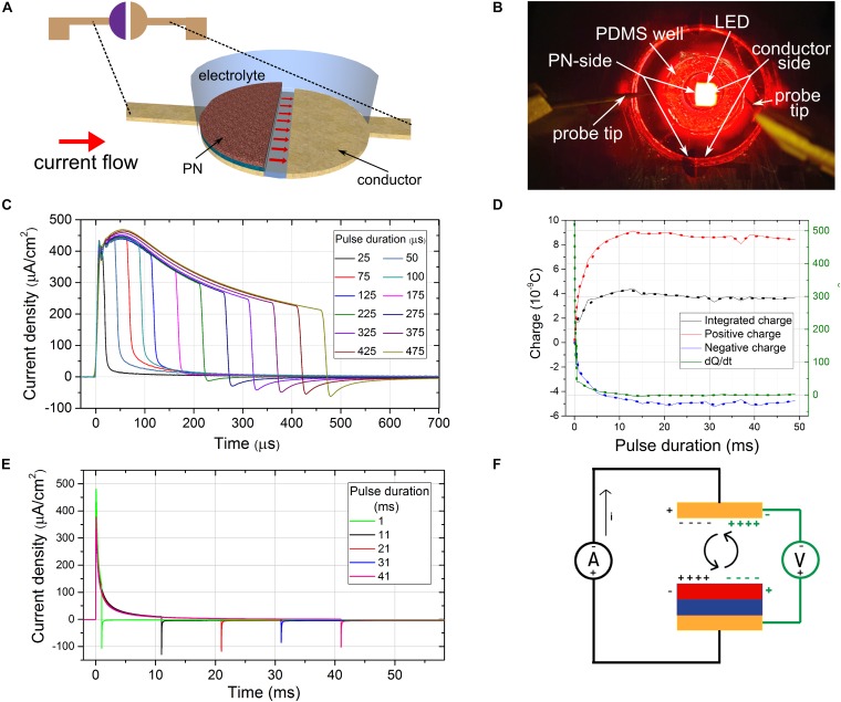
FIGURE 2.
Measuring time-resolved photocurrents of a floating optoelectronic stimulation device. (A) The split-architecture OEPC structure. Red arrows signify the current flow lines. (B) The measurement configuration showing the elastomer electrolyte-containment well on top of a split-OEPC device, with red LED light source in the background (C) current traces of a split-OEPC device under light excitation with sub-1 ms light pulses, 33 mW/cm2 intensity. (D) Total charge, charge delivered during the positive and negative current phase, and time derivative of the total charge delivered for long light pulses (E) current traces of a split-OEPC device under light excitation with pulses longer than 1 ms. (F) A proposed model of a floating OEPC charge dynamics in darkness (green) and under light excitation (black).

