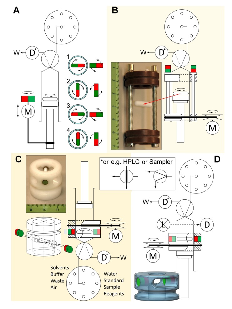
Figure 1.
Modalities for system setup, syringe orientation, and stirring arrangements. Stir-drivers are shown in photographs with a levitated magnetic stirring bar. (A,B,D): Syringe in upright orientation, (C) Syringe used upside down. (A) Stirring induced by a closely placed motor with an attached bar magnet, (B) Stir-driver for the full stroke length of the syringe, (C,D) Stir-driver for fixed position. Upon turning the stir-drivers via a rubber ring and motor, they generate a rotating magnetic field around the syringe barrel. Abbreviations D—Detector, L—Light source, M—Motor, W—Waste.

