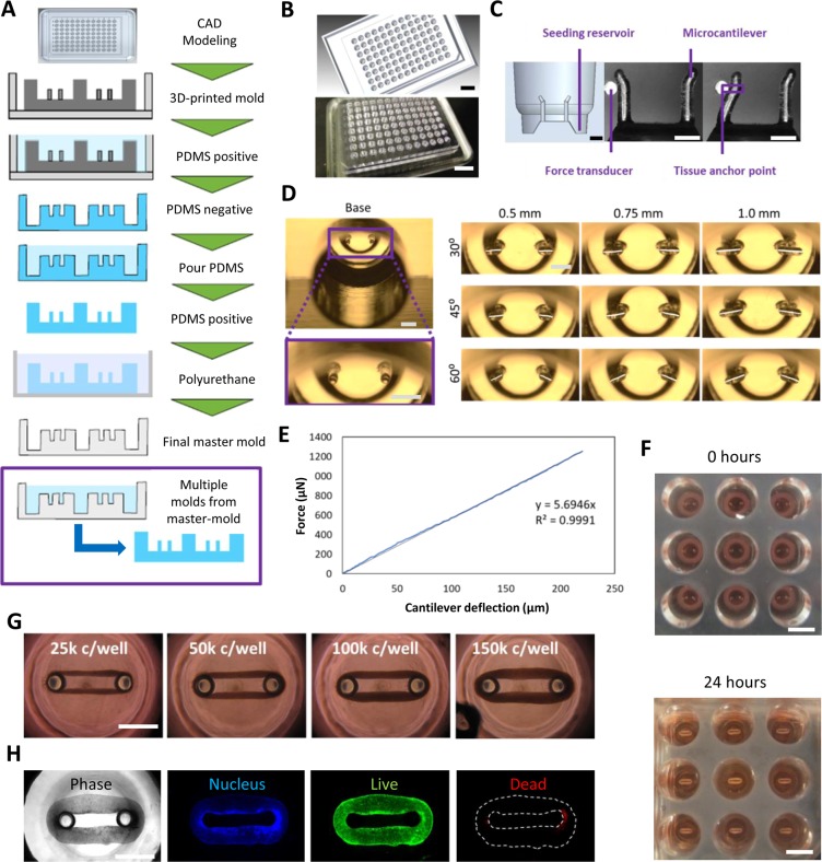
Figure 1.
Design and manufacture of Cardiac MicroRing (CaMiRi) platform. (A) Process flow of substrate manufacturing. The process started with creating a three-dimensional Computer Aided Design (3D CAD) model of the plate. The design is then printed using an Objet 30 Pro 3D printer to generate a positive mold. A negative PDMS mold is then created which is followed by a complementary positive PDMS mold. This positive PDMS mold is used to then create a polyurethane-based negative master mold which can be used to mold multiple PDMS plates. (B) 3D CAD model of a plate for 3D printing (top panel) and actual 3D-printed mold (bottom panel). Scale bars represent 20 mm. (C) Cross section of a well showing the seeding reservoir where cells are pipetted and the microcantilevers used for force-displacement measurement (empirically calibrated with a force transducer (Micro-Squisher) with tissue anchor points to hold microtissue in place. Scale bars represent 1 mm. (D) Tissue anchor angles and lengths were tested to determine optimal anchor geometry. Scale bars represent 1 mm. (E) Force-displacement curve of cantilevers as measured with the Micro-Squisher. (F) Cell-laden collagen seeded into reservoirs of CaMiRi device remodel into cardiac tissues tethered around microcantilevers within 24 hours. 9 wells of a 96-well plate containing CaMiRi are also shown. Scale bars represent 5 mm. (G) CaMiRi formulated from a range of total input cells (25,000; 50,000; 100,000; and 150,000 cells seeded per well. Scale bars represent 1 mm. (H) Live/dead staining of CaMiRi. From left to right: bright field, nuclei in blue, live cells in green, and dead cells in red. Scale bars represent 1 mm.

