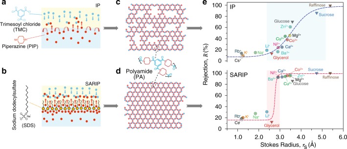
Fig. 1. Conventional IP vs. SARIP.
Schematic illustration of (a) the conventional IP and (b) SARIP. In both cases, PIP molecules in aqueous phase diffuse across the water/hexane interface to react with TMC in the hexane phase. In SARIP, SDS molecules added into the aqueous phase form a self-assembled dynamic network at the interface and regulate the interfacial transport of PIP. (c, d) Schematic illustrations of the PA active layer formed via conventional IP (top), which has a heterogeneous pore size distribution, and SARIP (bottom), which has a uniform pore size distribution. (e) Rejection of different solutes (circles for cations and inverted triangles for neutral organics) as a function of the Stokes radius for the PA membranes fabricated using conventional IP (top) and SARIP (bottom). Ion rejection vs. hydrated radius is also presented in Supplementary Fig. 1 and Supplementary Table 1, which demonstrates a qualitatively similar comparison between the two PA membranes as shown here. The aqueous SDS concentration in SARIP is 2.1 mM. The rejection of different species was measured from NF experiments with the respective membranes using a cross-flow filtration cell with an operating pressure of 4 bar and a crossflow velocity of 2.9 cm s−1. Rejection data of each solute represents the average of three runs and error bar represents the standard deviation of three replicate measurements.

