
Fig. 2.
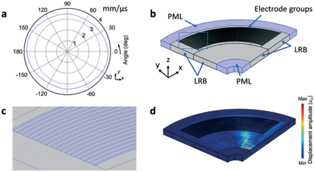
The finite element model used to simulate CSFIT. (a) Direction-dependent phase velocity cθ of SAWs in the X-cut LiNbO3 substrate. (b) Schematic of the simulation setup. The finite element model is composed of a 0.8 mm-thick X-cut LiNbO3 substrate with a CSFIT that has two groups of electrodes. (c) Zoom-in view of electrodes. (d) 3D simulation of the displacement field uz for the travelling SAW generated at the excitation frequency of 13.5 MHz.