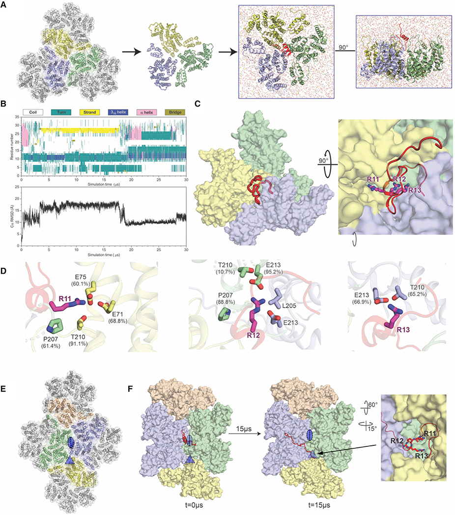
Figure 4. All-Atom Molecular Simulations Identify MxB Interactions at the Tri-hexamer Interface.
(A) The all-atom model of MxB1–35 at the tri-hexamer interface. Three dimers from different hexamers are in blue, yellow, and green (left). The MxB1–35 peptide in red is placed above the middle of the tri-hexamer region before simulations (right).
(B) The dynamics of MxB1–35 in tri-hexamer interface. The evolution of MxB secondary structure (top) during the simulation, computed by the STRIDE program in VMD and the root-mean-square deviation (RMSD) plot of the MxB Cα atoms (bottom).
(C) MxB1–35 (red) binds in the tri-hexamer interface. The MxB 11RRR13 motif is shown in magenta sticks.
(D) Molecular contacts between the MxB 11RRR13 motif and experimentally tested CA residues are shown for R11 (left), R12 (middle), and R13 (right), with corresponding contact occupancies.
(E) In a second simulation, the MxB peptide was initially placed at the interface between two CA hexamers (blue/green). The di- and tri-hexamer interfaces are marked by an oval and a triangle, respectively.
(F) Still images from the second simulation at the beginning and after 15 μs reveal that the MxB peptide again migrates to the tri-hexamer interface. The CA-binding 11RRR13 motif is shown in red sticks (right).
See also, Figure S5.

